利用OPENPLC开源代码将Raspberry Pi变成PLC
Installing required packages
Your RaspberryPi must be running Raspbian Jessie in order to install the OpenPLC. If you haven't updated yet, you must do so before installing this software.
1) Install WiringPi according to the instructions on their website.
2) Install the following packets using apt-get:
sudo apt-get update
sudo apt-get install build-essential pkg-config bison flex
sudo apt-get install autoconf automake libtool make nodejs git
3) Clone the OpenPLC repository on github by typing:
git clone
git clone https://github.com/thiagoralves/OpenPLC_v2.git
4) Enter in the OpenPLC_v2 directory and build the project (it may take a while):
cd OpenPLC_v2
./build.sh
At the end of the build process, you will be asked to choose an I/O driver to use with the OpenPLC:
The OpenPLC needs a driver to be able to control physical or virtual hardware.
Please select the driver you would like to use:
1) Blank 4) RaspberryPi 7) ESP8266
2) Modbus 5) UniPi 8) Arduino+RaspberryPi
3) Fischertechnik 6) Arduino 9) Simulink
#?
Select option 4 to use the RaspberryPi header pins as I/O.
Running the OpenPLC
The OpenPLC application has a NodeJS webserver that controls if the OpenPLC is running or not and enables the user to upload programs (.st) files generated using the PLCopen Editor to the OpenPLC. To start, enter in the OpenPLC_v2 directory and type:
sudo nodejs server.js
Now, just point your browser to http://ip-address-of-your-RaspberryPi:8080. You will see a web interface that will let you upload new programs to the OpenPLC. When a new program is uploaded, it is automatically compiled into a new application and executed.
Pin Mapping
Below you will find the OpenPLC I/O mapping for the Raspberry Pi header. The mapping should be the same across all the different board revisions.
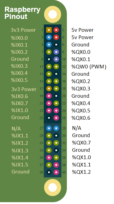
There is only one analog (PWM-based) output on the Raspberry Pi, and it is used as the an Analog Out (%QW0.0) on the OpenPLC. Also, take note that the first two inputs (%IX0.0 and %IX0.1) have hardware pullups, which means that if you don't connect anything to them, they will both read as TRUE. This is part of the design of the Raspberry Pi boards, and can't be changed by the OpenPLC software. Therefore, the logic on these first two inputs must be reverse.
Running the first project
This is a simple hello world project for the OpenPLC. The button is attached to %IX0.0 and the lamp is attached to %QX0.0. When the button is pressed and released, the lamp remains on for 2 seconds and then turns off.
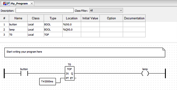
nerate Program in order to compile the diagram into a ST file. Then upload the ST file to the OpenPLC using the web interface.
PS: For the Raspberry Pi, this program needs to be slightly modified because the first two inputs actually have hardware pullups on the board. You need to either use another input (%IX0.2, %IX0.3, ...), or negate the button contact on the ladder logic for it to work properly.
相关链接
除特别注明外,本站所有文章均为EPLANP8原创,转载请注明出处来自http://www.eplanp8.com/3890.html

- 1 个人已赞